The Analog of Things Part 2

<< Previous: The Analog Of Things - Part 1
Introduction
The LM35 has been with us for a while, and when searching you may assume that it's something only recently from Arduino days - no it's from way back when. What makes the LM35 useful is that it's a straightforward device to use, and it comes in a variety of packages. These options enable the device to be accommodated in several settings from directly on the PCB, to mounting the device to the equipment or the item whose temperature is being measured.
The LM35 is not the only useful option, and we will also have a look at the MCP9700 as a contrast in a follow-up article.
Specifications
When considering a sensor, the sensor's specifications should also factor in.
- Temperature Range
- Resolution
- Accuracy
- Operating voltage
These factors translate into:
- The LM35 will measure between 0'C and 100'C, and this is suitable for most domestic applications.
- The resolution is 10mV /'C which means that every degree between 0'C and 100'C would be equal to OutPut V = 0.01 * T'c. At room temperature (23'C), the output voltage of the sensor would be ~0.230 V or 230mV.
- The device's accuracy is +/- 1'C across its temperature range
- The LM35 has an operational voltage of ~5Vdc.
Implementation Options
For the implementation options, we will review
- Which package to select
- Connecting the LM35, and interfacing with the PIC Microcontroller
- How to ensure a stable temperature measurement
The Right Package
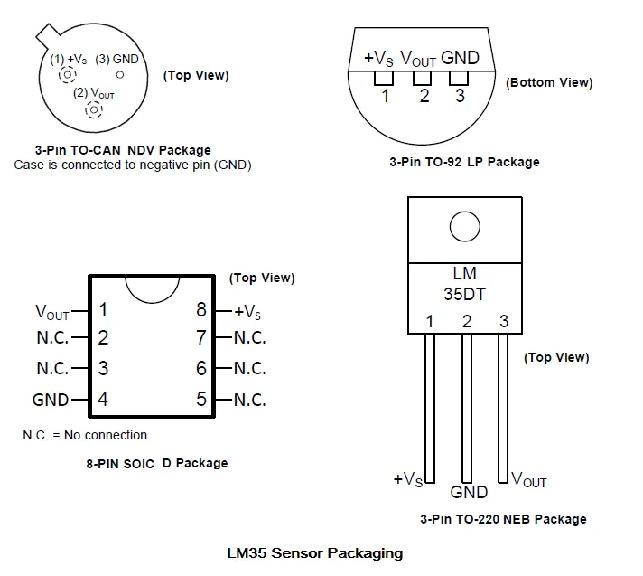
The LM35 is available in a number of 3 PIN transistorized packages. Show below is the diagrams and their variations. We will be using the 3-PIN TO-92 package as it's the easiest to work with and is fairly common to obtain.
Device Connection
Now that you have chosen the package type, the next step would be connecting it to the microcontroller. There are two options here, namely a direct connection and a buffered one.
If the LM35 sensor is situated some distance from the board, there will be a voltage drop. A voltage follower amplifier should assist with maintaining the right voltage output.
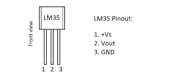
The device has three connections as shown in the image below. The Vout pin would be connected in one of two ways.
- Directly to the input PIN
- Through buffering circuitry
Stability
The output voltage which is later converted to the temperature may be subject to fluctuation owing to the device generating heat as current passes through it. If the sensor were used for a critical application, it may be advisable to include a method that disconnects the sensor from its power source ie, do not run the device continuously.
Power the sensor to take a reading or multiple readings over a short time frame and then switch off allowing it to "cool down" or return to the ambient temperature.
Software Implementation
Shown below is an example written for the PIC16F887, which we will also update for the "Passing the Torch" series. To make the code more useful, it sends the temperature result to the serial port.
The example is straightforward, with minimal configuration of the A2D required, as this is all handled by the library available in the compiler.
unsigned char ch;
unsigned int adc_rd;
char *text;
long tlong;
char *tempc = "000.0";

void main() {
  INTCON = 0;                              // disable all interrupts
  ANSEL  = 0x04;                           // Configure AN2 pin as analog input
  TRISA  = 0x04;
  ANSELH = 0;                              // Configure other AN pins as

  text = "LM35 Example";                   // assign text to string
  text = "LCD example";                    // assign text to string


  ADCON1     = 0x82;                       // configure VDD as Vref, and analog channels
  TRISA      = 0xFF;                       // designate PORTA as input
  Delay_ms(2000);
  text  = "voltage:";                      // assign text to string

  UART1_Init(9600);
  Delay_ms(100);

  while (1) {
    adc_rd  = ADC_read(2);                 // get ADC value from 2nd channel

    tlong = (long)adc_rd * 5000;           // covert adc reading to milivolts
    tlong = tlong / 1023;                  // 0..1023 -> 0-5000mV

    ch     = tlong / 1000;                 // extract volts digit
    tempc[1] = ch+48;

    ch    = (tlong / 100) % 10;            // extract 0.1 volts digit
    tempc[2] = ch+48;

    ch    = (tlong / 10) % 10;             // extract 0.01 volts digit
    tempc[3] = ch+48;
    tempc[4] = ch+48;


    UART1_Write(tempc[2]);
    UART1_Write(tempc[3]);
    UART1_Write_Text(".");
    UART1_Write(tempc[4]);

    UART1_Write(13);
    UART1_Write(10);
    Delay_ms(100);

    Delay_ms(1000);
  }
}//~!
Parts List
An LM35 is needed and a PIC Development board. To specifically use the PIC16F887, then you would require a Radix Duo or Radix Sepia. However, any of the Radix series would work with this project owing to its simplicity. However, some code modifications would be required depending on the Radix and IC chosen.
That is all for now, more to come in the next installment of The Analog of Things Part 3